November 27, 2016
Breadboard
Simple Breadboard
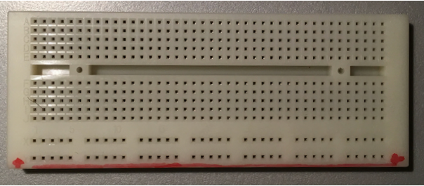
A breadboard has many holes, normally spaced 0.1” apart that you can insert leads/wires into. These will be kept in place by metal contacts inside the board. This allows fast prototyping of circuits, without the need to solder anything together.
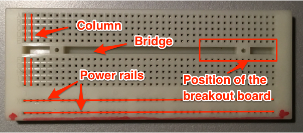
As shown in the image below a breadboard has many columns. All holes in one column are connected together internally, i.e. putting two wires into the same column connects them electrically to each other. There is also a so called bridge in the centre which separates one side of the board from the other both physically and electrically. If you attach a breakout board, it is very important that the two rows of pins go on opposite sides of this bridge.
Internal wiring of a Breadboard
A breadboard will normally have two long rows (sometimes even two on each side). These run the whole board length (or should be clearly marked if in sections). Those two rows are often referred to as power rails and are usually used to provide easy access to ground and power from position of the board.
I marked my outer power rail with a red line on the board (see upper picture). I always connect this rail to power, the other one to ground. The color makes it easier for me never to confuse it with ground. Some breadboards come with colored power rails out of the box.